Features:
The onboard two set power supply interface VCC5 5V power supply, VCC4 interface, 3.5--4.5V power supply, optional power on self starting (default) and control start.
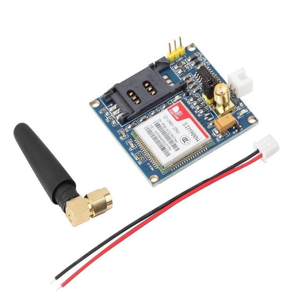
The onboard SMA (default) and IPXmini antenna interface, SIM900A interface reserved reset.
The size of the module is 49*50, all the new and original device.
The computer can give early computer debugging USB module power supply, a very large amount of data under the condition of the recommended current more than 1A. Standby dozens of MA data can be set to provide dormancy, dormancy of 10MA low power. Support 2, mobile phone 3,4G card.
The serial port circuit: support for 3.3V single chip microcomputer. TTL serial port support
3.3 and 5V single chip microcomputer.
The SIM card circuit to increase the SMF05C ESD chip.
Antenna circuit: guarantee short and straight, so as to ensure the signal strength.
PCB display screen printing mark: each interface, convenient development two times, the SIM900/A hardware is completely follow the design when the design manual.
Two power supply interface: VCC5, 5V DC above 1A. Computer 5V power supply can be early computer USB. DC long data circuit over larger recommended 5V1A. VCC4, 3.5--4.5V power supply, ibid., suitable for lithium battery.
Control pin all leads.
A TTL level, compatible with 3.3V and 5V.
The two antenna interface, the default SMA straight head, connector for IPXmini antenna.
One way of speech interface, the way Mike interface.
The control interface of each pin description:
GND - GND
SIMR SIM900A RXD, TTL level, can not be directly connected to the 232 level
SIMT SIM900A TXD, TTL level, can not be directly connected to the 232 level
RST - SIM900A reset, active low
VCC_MCU when the SIM900A module and 5V TTL level communication, this pin is connected to DC 5V; when the level of communication of SIM900A and 3.3V TTL, this pin is connected to DC 3.3V.
VCC5----DC 5V input.
VCC4------DC3.5--4.5 input
Onboard Resources:
Serial port circuit(with protection)
Antenna interface circuit(SMA bend female port)
SIM card circuit(flip SIM slot)
4*3.5 fixture hole 4pcs
SIM900A serial port output terminal
Specifications:
Size:49mm x 47mm
Net Weight:28g
Weight: 38g
Wiring
A TTL level, compatible with 3.3V and 5V.
The two antenna interface, the default SMA straight head, connector for IPXmini antenna.
One way of speech interface, the way Mike interface.
The control interface of each pin description:
GND - GND
SIMR SIM900A RXD, TTL level, can not be directly connected to the 232 level
SIMT SIM900A TXD, TTL level, can not be directly connected to the 232 level
RST - SIM900A reset, active low
VCC_MCU when the SIM900A module and 5V TTL level communication, this pin is connected to DC 5V; when the level of communication of SIM900A and 3.3V TTL, this pin is connected to DC 3.3V.
VCC5----DC 5V input.
VCC4------DC3.5--4.5 input
Green wire : RX
Gray wire : TX
External power supply
RX,TX connect to 2,3
External power supply 5 volt
///////////////////////////////////AT command\\\\\\\\\\\\\\\\\\\\\\\\\\\\\\\\\\\
Link here is AT command document 👇👇
****************CODE****************
Test send message using AT command
#include <SoftwareSerial.h>
SoftwareSerial sim900a(7, 8); // 7=RX, 8=TX // GSM TX SHOULD CONNECT TO 2, GSM RX SHOULD CONNECT TO 3
void setup() {
Serial.begin(9600);
sim900a.begin(9600);
}
void loop()
{
delay(1000);
send_test_sms();// SEND TEST SMS
}
void send_test_sms()
{
sim900a.print("AT\r");//
delay(500);
sim900a.print("AT+CMGF=1;\r"); // select message mode
delay(500);
sim900a.print("AT+CMGS=\"0843545xxx\";\r"); // ENTER YOUR RECEIVER PHONE NO
delay(500);
sim900a.print("I AM GSM AND SENDING SMS TEST SMS");// message data , you can send variables , strings or any kind of other data
sim900a.print("\r");
delay(1000);
sim900a.println((char)26);
sim900a.write(0x1a);// CTRL+Z SENDING CODE CTRL+Z=0x26
}
😃😃😃😃😃😃😃😃😃😃Add sensor 😃😃😃😃😃😃😃😃
#include <SoftwareSerial.h>
SoftwareSerial sim900a(7, 8); // 7=RX, 8=TX // GSM TX SHOULD CONNECT TO 7,
GSM RX SHOULD CONNECT TO 8
// wet sensor para
const int analogInPin = A0; // Analog input pin that the potentiometer is attached to
const int analogOutPin = 9; // Analog output pin that the LED is attached to
int sensorValue = 0; // value read from the pot
int outputValue = 0; // value output to the PWM (analog out)
///////////////////////////////////////////////////
void setup() {
Serial.begin(9600);
sim900a.begin(9600);
}
void loop()
{
delay(1000);
send_test_sms();// SEND TEST SMS
//WetSensor();
}
void send_test_sms()
{
sim900a.print("AT\r");//
delay(500);
sim900a.print("AT+CMGF=1;\r");// select message mode
delay(500);
sim900a.print("AT+CMGS=\"your phone no. \";\r");// RECEIVER PHONE NO HERE
delay(500);
// read the analog in value:
sensorValue = analogRead(analogInPin);
// map it to the range of the analog out:
outputValue = map(sensorValue, 0, 1023, 0, 255);
// change the analog out value:
analogWrite(analogOutPin, outputValue);
// print the results to the Serial Monitor:
Serial.print("sensor = ");
Serial.print(sensorValue);
Serial.print("\t output = ");
Serial.println(outputValue);
// wait 2 milliseconds before the next loop for the analog-to-digital
// converter to settle after the last reading:
delay(100);
if(sensorValue < 500) //
{
sim900a.print("Flooding warnign !!! ");
sim900a.print("\r");
delay(1000);
sim900a.println((char)26);
sim900a.write(0x1a);// CTRL+Z SENDING CODE CTRL+Z=0x26
}
}


 MAP I/O Wiring Node MCU >> GPS D1 (GPIO 5) >> RX ...