วันเสาร์ที่ 28 เมษายน พ.ศ. 2561

Arduino Hydroponic

      เมื่อเราต้องการที่จะปลูกผัก H้ydroponic ด้วยเหตุผลอะไรก็สุดแล้วแต่ไม่ว่าจะเพื่อกินเองหรือเพื่อขาย หรือเพื่อเป็นการผ่อนคลายยามว่ามันก็จะต้องมาพิจารณาว่าเราจะมีเวลาที่จะปลูกแค่ไหนหรือ  เราจะปลูกมันอย่างไร จากวัสดุอะไร ในยุคปัจจุบันผม ได้เห็นแล้วว่าเมื่อเราอยุ่ในเมืองมันมีข้อจำกัดจริงๆในการที่จะปลูกอะไรซักอย่างมันมีทั้งพื้นที่และเวลา ในการดูแลที่จำกัดเมื่อเราคิดว่าจะทำก้ต้องลองดูซักตั้งเพื่อเป็นการพิสูจน์ว่าเราไม่ใช่คนไก่กา  แต่พอมาลองจะทำดูก็จะมีเหตุให้เป็นอันทำไม่เสร็จซื้อของมาไม่ครบ ต้องวิ่งรถไปร้านขายหลายรอบ บางทีอาจยกเลิกไปเลยเสียเงินเสียเวลา โดยเฉพาะในยุคนี้ยุคที่เวลามีค่ามากกว่าเงินทอง เรายอมจ่ายเงินค่าธรรมเนียมต่างๆแลกกับการเสียเวลารอคิวถูกไหมครับนั่นแหละที่เขาเรียกว่าเวลาเป็นเป็นทอง  ผมเลยอยากแนะนำเพื่อนๆ ถ้าคิดจะทำลองพิจารณาซื้อชุดสำเร็จรูปตัวนี้ไปใช้ได้เลยตามลิ้งข้างล่าง  ครบชุดพร้อมปลูก


ชุดนี้เขาขายที่ LAZADA ลองเข้าไปดูนะครับ ผมว่ากับราคา 1750 บาทคุ้มค่ามากๆ ดูในชุดที่ให้มาผมเอาข้อมูลมาให้เพื่อนๆดู มันให้แม้กระทั้งเม็ดผัก มีปั้มน้ำด้วย ก็คิดว่าเหมาะสำหรับคนที่ชอบอะไรที่คุ้มค่าๆหรือแบบ เห็นชุดนี้แล้วไม่ต้องคิดไรมากเลย ผมกำลังจะจัดมาเหมือนกันเพราะว่าจะเอามาทำชุดปลูกอัตโนมัติ


รายละเอียดสินค้า

ชุดปลูกผักไฮโดรโปนิกส์ รุ่น set12
รายละเอียดสินค้า
ชุดปลูกผักHydroponic รุ่น Hydro12
 โครงโต๊ะ PVC สีขาว ขนาด 50 x 50 x 40 cm
2.รางปลูกผักไฮโดรโปนิกส์ ความยาว 60 cm จำนวน 3 ราง
3.ชุดท่อส่งสารละลายธาตุอาหาร พร้อมวาล์วเปิดปิด 3 ตัว
4.ชุดท่อรวมสารละลายอาหาร
5.สารละลายธาตุอาหาร ปุ๋ย A และ B อย่างละ 500 ซีซี
6.ไซริ้งค์ 1 อัน
7.ถ้วยตวงน้ำ 1 ใบ
8.ถาดเพาะเมล็ด 1 ใบ
9.ฟองน้ำ 1 แผ่น
10.ถ้วยปลูกเขียว 36 ใบ
11.ถ้วยปลูกใช้ซ้ำ 24 ใบ
12.เคเบิ้ลไทด์ 1 เส้น
13.เมล็ดผักสลัด 100 เมล็ด
14.เมล็ดกวางตุ้ง 100 เมล็ด
15.ปั๊มน้ำ 1 ตัว
16.ถังน้ำ 1 ใบ
17.สายยาง 2 เส้น
18.เข็มขัดรัดท่อ 1 ตัว
19.คู่มือการปลูกผักไฮโดรโปนิกส์


เมื่อได้ชุดปลูกแล้วก็เหลือแต่ชุดควบคุมอัตโนมัติ ซึ่งเราจะต้องมาทำกันขึ้นมา โดยแนวคิดคือ เราจะต้องให้ปุ๋ยกับผักอย่างสม่ำเสมอ มีการควบคุมค่า ph จ่ายน้ำเลี้ยงอย่างต่อเนื่อง ทีนี้แต่ละเรื่องที่เราจะต้องจัดการเรามาลำดับกันเป็นขั้นตอนกันดังนี้นะครับ

อุปกรณ์

ESP8266  Node MCU
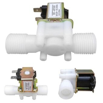
Solenoid valve
Relay
ph sensor
Conduct sensor


Buy Now


Features:
*Electric solenoid valve, 100% Brand New and durable.
*Material:Metal + plastic
*Color: As Pictures Show
*Screw diameter: approx. 20mm/0.79’’;
Size: approx. 84 * 57mm/3.31’’x2.24’’ (L x H);
Coil size: approx. 34 * 23mm/1.34’’x0.91’’ (W x H)
*Usage: water and low viscosity fluids
Specifications:
*Voltage: DC 12V
*Power: 8W
*Current: 0.6A
*Inlet and outlet: hose barbs for 1/2" (outer diameter) hose
*Pressure: 0.02- 0.8Mpa
*Max fluid temperature: 100°C
*Operation mode: normally closed
Package Contents
1*Electric solenoid valve


VDO How to create BLYNK


Wiring Diagram


Arduino Code

#include <Adafruit_Sensor.h>

/*************************************************************
  Download latest Blynk library here:
    https://github.com/blynkkk/blynk-library/releases/latest

  Blynk is a platform with iOS and Android apps to control
  Arduino, Raspberry Pi and the likes over the Internet.
  You can easily build graphic interfaces for all your
  projects by simply dragging and dropping widgets.

    Downloads, docs, tutorials: http://www.blynk.cc
    Sketch generator:           http://examples.blynk.cc
    Blynk community:            http://community.blynk.cc
    Follow us:                  http://www.fb.com/blynkapp
                                http://twitter.com/blynk_app

  Blynk library is licensed under MIT license
  This example code is in public domain.

 *************************************************************

  This example shows how value can be pushed from Arduino to
  the Blynk App.

  WARNING :
  For this example you'll need Adafruit DHT sensor libraries:
    https://github.com/adafruit/Adafruit_Sensor
    https://github.com/adafruit/DHT-sensor-library

  App project setup:
    Value Display widget attached to V5
    Value Display widget attached to V6
 *************************************************************/

/* Comment this out to disable prints and save space */
#define BLYNK_PRINT Serial

#include <ESP8266WiFi.h>
#include <SPI.h>
//#include <Ethernet.h>
#include <ESP8266WiFi.h>  
//#include <BlynkSimpleEthernet.h>
#include <BlynkSimpleEsp8266.h>
#include <DHT.h>
#include <Wire.h>
#include <LiquidCrystal_I2C.h>
LiquidCrystal_I2C lcd(0x27, 16, 2);


// You should get Auth Token in the Blynk App.
// Go to the Project Settings (nut icon).
char auth[] = "6dfbf92a8cdd4f18b30347ee9ed1789e";
char ssid[] = "santi";  //user WIFI 
char pass[] = "santi12345678"; // password WIFI 


#define DHTPIN D3          // What digital pin we're connected to

// Uncomment whatever type you're using!
#define DHTTYPE DHT11     // DHT 11
//#define DHTTYPE DHT22   // DHT 22, AM2302, AM2321
//#define DHTTYPE DHT21   // DHT 21, AM2301


DHT dht(DHTPIN, DHTTYPE);
BlynkTimer timer;

// This function sends Arduino's up time every second to Virtual Pin (5).
// In the app, Widget's reading frequency should be set to PUSH. This means
// that you define how often to send data to Blynk App.


void sendSensor()
{
  float s = analogRead(A0);
  float h = dht.readHumidity();
  float t = dht.readTemperature(); // or dht.readTemperature(true) for Fahrenheit
lcd.begin();
lcd.backlight();
lcd.setCursor(0,0);
lcd.print("Humi:");
lcd.setCursor(5,0);
lcd.print(h);
lcd.setCursor(0,1);
lcd.print("Temp:");
lcd.setCursor(5,1);
lcd.print(t);
lcd.setCursor(8,0);
lcd.print("Soi:");
lcd.print(s);
  if (isnan(h) || isnan(t)) {
    Serial.println("Failed to read from DHT sensor!");
    return;
  }
  // You can send any value at any time.
  // Please don't send more that 10 values per second.
  Blynk.virtualWrite(V5, h);
  Blynk.virtualWrite(V6, t);
}

void setup()
{
  // Debug console
  Serial.begin(9600);

  Blynk.begin(auth, ssid, pass);

  dht.begin();

  // Setup a function to be called every second
  timer.setInterval(10000L, sendSensor);
  lcd.begin();
  lcd.backlight();


}

void loop()
{
  Blynk.run();
  timer.run();


}


วันอาทิตย์ที่ 22 เมษายน พ.ศ. 2561

Smart home Energy conservation .


Equipment

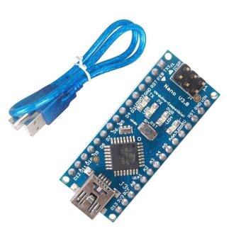
1. Arduino NANO


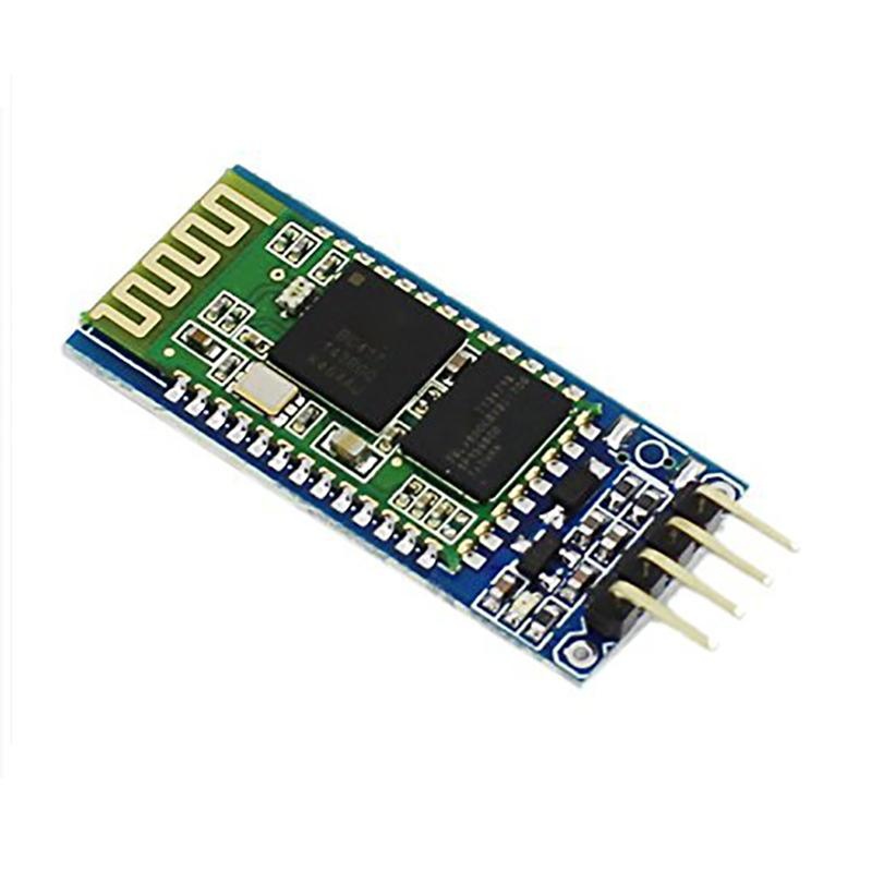
2.HC-06 Bluetooth module


3. 4 relays


code

#include<SoftwareSerial.h>
SoftwareSerial mySerial(10,11);//rx,tx
//const int LDR=A0;
//int xx;

int Light   = 2;
int Loundry  = 3;
int TV   = 4;
int Radio   = 5;
char  receivedChar;


void setup() {
 // Serial.begin(19200);
  mySerial.begin(9600);
  pinMode(Light,OUTPUT);
  pinMode(Loundry,OUTPUT);
  pinMode(TV,OUTPUT);
  pinMode(Radio,OUTPUT);

             digitalWrite(Light,HIGH); 
             digitalWrite(Loundry,HIGH);//setting motorA's directon
             digitalWrite(TV,HIGH);
             digitalWrite(Radio,HIGH);//setting motorB's directon
  
  
}

void loop()

{


// xx = analogRead(LDR); 
// mySerial.print(xx);

//Serial.println(xx);
 // delay(500);

   while (!mySerial.available());   // stay here so long as COM port is empty

  receivedChar = mySerial.read();

  if (receivedChar == 'A') {

            //digitalWrite(ENA,LOW);
            // digitalWrite(ENB,LOW);// High is start driving car
              
             digitalWrite(Light,LOW);
             Serial.println(receivedChar);
            
  }
              
  if (receivedChar == 'B') {

             // digitalWrite(ENA,LOW);
             // digitalWrite(ENB,LOW);// High is start driving car


             digitalWrite(Loundry,LOW);
            
                         
  }      
  if (receivedChar == 'C') 
  
              {

             // digitalWrite(ENA,LOW);
             // digitalWrite(ENB,LOW);// High is start driving car
  
             digitalWrite(TV,LOW);


  } // if it is a 3 flash the LED

  if (receivedChar == 'D') {
  
              //digitalWrite(ENA,LOW);
              //digitalWrite(ENB,LOW);// High is start driving car
              
                          
             digitalWrite(Radio,LOW);
             

  } // if it is a 4 print out lots of sensor data


  if (receivedChar == 'E') {
  
             
             digitalWrite(Light,HIGH); 

  }

   if (receivedChar == 'F') {
  
             
             digitalWrite(Loundry,HIGH);//setting motorA's directon

  }

   if (receivedChar == 'G') {
  
             
             digitalWrite(TV,HIGH);

  }


   if (receivedChar == 'H') {
  
             
             digitalWrite(Radio,HIGH);//setting motorB's directon

  }


  }


mit 

วันพุธที่ 11 เมษายน พ.ศ. 2561

MIT APP Inventor received data from Arduino + Bluetooth HC06

Equipment

1. Arduino NANO


คลิ้กดูรายละเอียด Arduino NANO ได้เลย


2.HC-06 Bluetooth module


3.LDR


                                                Wiring

NANO        to         HC-06

D10                             TX
D11                              RX

NANO                      LDR
A0                             A0


CODE


#include<SoftwareSerial.h>
SoftwareSerial mySerial(10,11);//rx,tx
const int LDR=A0;
int xx;
void setup() {
 // Serial.begin(19200);
  mySerial.begin(9600);
 // pinMode(LDR,INPUT);
  
}

void loop()

{

 xx = analogRead(LDR); 
 mySerial.print(xx);

//  Serial.println(xx);
  delay(500);
}


MIT Appication Inventor


วันจันทร์ที่ 12 มีนาคม พ.ศ. 2561

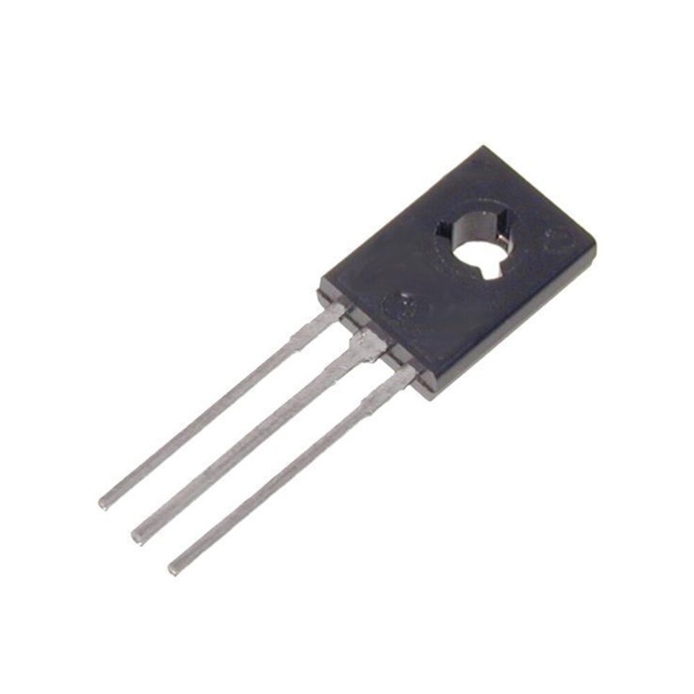
Arduino NANO+BD139 NPN Transistor+Speed control


credit:  www.likecircuit.com


Analog in


PWM pin out


Code


int BD139_Pin = 5;      // LED connected to digital pin 9
int analogPin = A3;   // potentiometer connected to analog pin 3
int val = 0;         // variable to store the read value

void setup()
{

   Serial.begin(9600);
  // Serial.println("CLEARDATA");
  pinMode(BD139_Pin, OUTPUT);   // sets the pin as output
}

void loop()
{
  val = analogRead(analogPin);   // read the input pin
  val=val/4;
  analogWrite(BD139_Pin, val);  // analogRead values go from 0 to 1023, analogWrite values from 0 to 255
// Serial.print("DATA,TIME,");
Serial.println(val);
delay(100);

}


วันพฤหัสบดีที่ 8 กุมภาพันธ์ พ.ศ. 2561

ESP8266 Access point scanner Show LCD


#include <Wire.h>
#include <LiquidCrystal_I2C.h>

// Set the LCD address to 0x27 for a 16 chars and 2 line display
LiquidCrystal_I2C lcd(0x27, 16, 2);


#include "ESP8266WiFi.h"

void setup() {
  Serial.begin(115200);

  // Set WiFi to station mode and disconnect from an AP if it was previously connected
  WiFi.mode(WIFI_STA);
  WiFi.disconnect();
  delay(100);

  Serial.println("Setup done");

  // initialize the LCD
  lcd.begin();
}

void loop() {
  Serial.println("scan start");

  // WiFi.scanNetworks will return the number of networks found
  int n = WiFi.scanNetworks();
  Serial.println("scan done");
  if (n == 0)
    Serial.println("no networks found");
  else
  {
    Serial.print(n);
    Serial.println(" networks found");
    for (int i = 0; i < n; ++i)
    {
      // Print SSID and RSSI for each network found
      Serial.print(i + 1);
      Serial.print(": ");
      Serial.print(WiFi.SSID(i));
      Serial.print(" (");
      Serial.print(WiFi.RSSI(i));
      Serial.print(")");
      Serial.println((WiFi.encryptionType(i) == ENC_TYPE_NONE)?" ":"*");
      delay(1000);

// LCD

      lcd.setCursor(0,0);
      lcd.print(i + 1);
      lcd.setCursor(0,1);
      lcd.print(WiFi.SSID(i));
     
     
    }
  }
  Serial.println("");

  // Wait a bit before scanning again
  delay(5000);
}

วันอังคารที่ 6 กุมภาพันธ์ พ.ศ. 2561

ESP8266 NODE MCU connect I2C LCD


Wiring


I2C LCD  to ESP8266 Node MCU

GND to GND
VCC to VU
SDA to D2
SCL to D1


use example code from IDE


#include <Wire.h> 
#include <LiquidCrystal_I2C.h>

// Set the LCD address to 0x27 for a 16 chars and 2 line display
LiquidCrystal_I2C lcd(0x27, 16, 2);

void setup()
{
// initialize the LCD
lcd.begin();
}

void loop()
{
bool blinking = true;
lcd.cursor();

while (1) {
if (blinking) {
lcd.clear();
lcd.print("No cursor blink");
lcd.noBlink();
blinking = false;
} else {
lcd.clear();
lcd.print("Cursor blink");
lcd.blink();
blinking = true;
}
delay(4000);
}

}


วันจันทร์ที่ 8 มกราคม พ.ศ. 2561

SHOW GPS to I2C LCD

Please watch this VDO First 


Hook up I2C LCD


I2C LCD

Connect

LCD >>> Arduino

GND  >>> GND
VCC  >>> 5Vcc
SDA  >>> A4
SCL   >>> A5

Code


#include <LiquidCrystal_I2C.h>
LiquidCrystal_I2C lcd(0x27, 16, 2);

#include<SoftwareSerial.h>
SoftwareSerial GPSModule(11,10); // RX,TX)
int updates;
int failedUpdates;
int pos;
int stringplace = 0;

String timeUp;
String nmea[15];
String labels[12] {"Time: ", "Status: ", "Latitude: ", "Hemisphere: ", "Longitude: ", "Hemisphere: ", "Speed: ", "Track Angle: ", "Date: "};
void setup() {
Serial.begin(57600);
GPSModule.begin(9600);

//LCD
lcd.init();
lcd.backlight();

lcd.setCursor(0,0);
lcd.print("A-arduino GPS");
lcd.setCursor(0,1);
lcd.print(nmea[8]);
lcd.setCursor(9,1);
lcd.print(nmea[0]);

delay(3000);


}

void loop() {
Serial.flush();
GPSModule.flush();
while (GPSModule.available() > 0)
{
GPSModule.read();

}
if (GPSModule.find("$GPRMC,")) {
String tempMsg = GPSModule.readStringUntil('\n');
for (int i = 0; i < tempMsg.length(); i++) {
if (tempMsg.substring(i, i + 1) == ",") {
nmea[pos] = tempMsg.substring(stringplace, i);
stringplace = i + 1;
pos++;
}
if (i == tempMsg.length() - 1) {
nmea[pos] = tempMsg.substring(stringplace, i);
}
}
updates++;
nmea[2] = ConvertLat();
nmea[4] = ConvertLng();
for (int i = 0; i < 9; i++) {
Serial.print(labels[i]);
Serial.print(nmea[i]);
Serial.println("");


lcd.setCursor(0,0);
lcd.print("lat :");

lcd.setCursor(5,0);
lcd.print(nmea[2]);

lcd.setCursor(0,1);
lcd.print("long:");
lcd.setCursor(5,1);
lcd.print(nmea[4]);

delay(1000);


}

}
else {

failedUpdates++;

}
stringplace = 0;
pos = 0;
}

String ConvertLat() {
String posneg = "";
if (nmea[3] == "S") {
posneg = "-";
}
String latfirst;
float latsecond;
for (int i = 0; i < nmea[2].length(); i++) {
if (nmea[2].substring(i, i + 1) == ".") {
latfirst = nmea[2].substring(0, i - 2);
latsecond = nmea[2].substring(i - 2).toFloat();
}
}
latsecond = latsecond / 60;
String CalcLat = "";

char charVal[9];
dtostrf(latsecond, 4, 6, charVal);
for (int i = 0; i < sizeof(charVal); i++)
{
CalcLat += charVal[i];
}
latfirst += CalcLat.substring(1);
latfirst = posneg += latfirst;
return latfirst;
}

String ConvertLng() {
String posneg = "";
if (nmea[5] == "W") {
posneg = "-";
}

String lngfirst;
float lngsecond;
for (int i = 0; i < nmea[4].length(); i++) {
if (nmea[4].substring(i, i + 1) == ".") {
lngfirst = nmea[4].substring(0, i - 2);
//Serial.println(lngfirst);
lngsecond = nmea[4].substring(i - 2).toFloat();
//Serial.println(lngsecond);

}
}
lngsecond = lngsecond / 60;
String CalcLng = "";
char charVal[9];
dtostrf(lngsecond, 4, 6, charVal);
for (int i = 0; i < sizeof(charVal); i++)
{
CalcLng += charVal[i];
}
lngfirst += CalcLng.substring(1);
lngfirst = posneg += lngfirst;
return lngfirst;
}


วันศุกร์ที่ 5 มกราคม พ.ศ. 2561

PIR sensor+Arduino เซนเซอร์จับการเคลื่อนไหว


CODE


int ledPin= 9;
int inputPin= 2;

void setup(){
  pinMode(ledPin, OUTPUT);
  pinMode(inputPin, INPUT);

  Serial.begin(9600);
}

void loop(){
  int value= digitalRead(inputPin);
Serial.println(value);
  if (value == HIGH)
  {
    digitalWrite(ledPin, HIGH);
    delay(1000) ;
  }

  else
  {
    digitalWrite(ledPin, LOW);

delay(1000) ;
  }
}